First let’s shot the elephant in the room : it’s mostly off topic of this site.
Now that this is done, let’s talk about what it is.
So what is it ?
Simple, this is my project to build myself a mechanical keyboard from my dead MX Board 6.0.
Why is it dead in the first place ?
Good question myself. You see, it’s a quite common story involving sweat, hard work, and a not grounded soldering iron.
At first it should have been a “simple” change from MX red switches to MX white ones.
Years of membrane keyboards taught my fingers to try poke holes through them, and since I don’t see smashing keys hard as a negative I never tried to correct that. Needless to say that MX red are terribly too light for me (see I still said it for readers that are not into that kind of thing), even resting my finger on the keys when gaming was enough to activate them at time. That needed to stop.
So I ordered myself some Cherry MX white I could have gone for Kailh box navy, but since the keyboard is backlit I didn’t want even less light to be blocked.
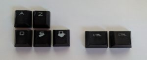
In the same time ordered new keycaps, some double-shot PBT compatible with backlight, my layout (ISO FR), and with the keyboard that I found by some miracle on aliexpress. You see the old ones were quite badly worn out as you can see, the D and S caps are really carved, that was due to my nails being quite long since I randomly stopped biting them this year.
So, yeah, also changing the switches and the keycaps at the same time in my mind sounded like a nice metamorphosis (and we all appreciate a good metamorphosis here 😉).
I was in the process of moving so I kinda lost my soldering iron the the process so I ordered a TS100, that was definetly a good decision, that thing is awesome.
So once arrived I started desoldering those switches. I only had desoldering wick and a fluxpen that I found in my stuff and boy that was messy ! Took me something like 3h to remove 9 switches. By the time I called it a night, because it was dusk and I didn’t want mosquitoes to suck me dry, I was starting to refine my desoldering skills with the wick.
But the result were still so underwelming, that I ordered a desoldering pump.
Once it arrived I started again, and after around 2h I started having my hand with it, and I also installed some mosquito net on my window so I continued until morning (I’m a bit of a nigh owl) once every switches and their LED were removed (that mean desoldering around 440 points and removing around 110 LED and switches which is deceptively hard at first) I cleaned a little the PCB and started installing the new ones.
Everything was “smooth” (not really but let’s go with that) so far except some traces I ruined the first day but nothing too critical.
Once every new switches were installed I tested the board, some issues were present : some switches that I forgot to solder, and a couple resistors pad that were bridging (the MX Board 6.0 uses a exotic design based on resistance to read the key pressed), after fixing them everything except the backlighting was working.
Then the trouble started, I installed the LEDs, trying not to make mistakes in their polarities aware of the fact that they were in series.
I failed. Nothing lit up.
Without a multimeter (remember, moving) I pulled a LED and used it to try to troubleshot the issue. It never worked, I saw some LEDs I mounted the wrong way, and turned them but still nothing I didn’t even manage to find the source of the current for the backlighting.
Then I saw yet another LED mounted in the wrong way and by them I already stopped to unplug the keyboard to solder on it. That probably was the mistake that lead to the disaster.
Early when desolreding everything I noticed that when I was in contact to the ground of the board and that I was touching the LED terminals when soldering them some lit up probably due to me and my iron not being grounded allowing a little AC to flow from the PWM of the soldering iron and my capacitive mass. That would be my guess anyway.
So when I was trying yet another time to fix the backlight my computer started going crazy, and the keyboard test software running told me that indeed I messed my keyboard PCB.
I think that due to the nature of the key reading the PCB was quite rugged, I must have shorted pretty much everything without causing any issue, that is why I think that it must be the soldering iron background AC that caused it. And by that I mean my mistake to solder while keeping the board plugged and my decision based on laziness to not bother grounding it.
So what then ?
After that I looked at the board annoyed by my stupidity, tried to look how it was made, on the logic side.
The issue is that the keyboard now spat inputs every milliseconds (as advertised that resistance based tech does work after all). My guess was that I either bridged the PWM of the backlight with the logic side or that I fried a component between the microcontroller and the keys, after checking for bridges, I sided with the fried something hypothesis.
The logic board being crammed in the space above the nav’ cluster arrows, I looked at the ICs, but nothing visible, so I now had a choice to make.
Buying blindly some replacement hoping that it was not a passive or part of the microcontroller that got fried (part because it was still working as a keyboard, a mad one, but a keyboard) in those cases I wasn’t skilled enough to fix it, swapping the other ICs would have already be hard enough due to their size and my lack of equipment to do reflow properly.
The other was to give up.
I was leaning to giving up when an idea stroke me.
Why not double down of the customization ?
Entering the “Shining Armor”
After frying the logic board I was now left with : my regrets, a useless PCB, a bunch new and old all functioning switches, a metal mounting plate, a cast alloy casing (supposed to be aluminium but still ferromagnetic) and a plastic backplate with still unbroken flipping feets (quite the feat since I broke them on all my previous keyboards, probably because of my hammer fingers).
That keyboard was built like a tank, if I would not shot at it with AP AC shells it would still be working.
Given the price of it and the fact that it was in fine only part of what made it a good keyboard that was destroyed I figured : why not just replace the PCB ?
I tried to look for a donor keyboard but since the model was considered overpriced at the time and not sold anymore. My quick search were in vain. But when looking at some specialized forum I read a topic about a drop-in replacement for an other Cherry keyboard, and I though : “hey that is not a bad idea”. I looked for a replacement for my keyboard, nothing, quite unsurprisingly for this quite unpopular design.
Then I found a tutorial about making you own design, and since I’m quite the type to learn how to do stuff I chose to go for it and make myself a custom drop-in replacement for my as-good-as-dead PCB.
By then I decided that the customization was heavy enough to justify the status of named project.
I chose “Shining Armor” because of the MX White switches. I figured that with all the metal and the white switches and the backlight, the theme of the “white knight in shining armor” does match, doesn’t it ? I mean it matches at least 4 words out of 5. But the name was too lengthy and the “white knight” part was already connoted on the internet so I kept the “shining armor” part. And I don’t mind naming it like a pony which is a prince consort in a matriarcal society.
Hum, kinda loop back to a SJW subject when you think about it …
Anyway I still think it’s a cool and adequate name.
My goals with the design
First I want to retain most of the features of the keyboard, that means.
- Keeping the plain colored backlight, maybe a smidge more fancy as long as it’s light on the programming and electronic side
- Keeping N-Key Roll Over, since it was that made me buy a new keyboard in the first place, I want to be able to roll my head on the keyboard and still have perfect inputs
- Keeping the same footprint, including the use of the backplate (kinda forced by the fact that I have switches for plate mounting anyway)
- Keeping the same dual color LEDs for toggleable button like num, caps and scroll locks
I will also try to :
- Keep the number of active components low while I don’t care about passives
- Use through holes components where I can since I’m not equipped for SMD
- Use 2 layer PCB, 4 layer could be easier to design but kinda overkill and pricier
However I must say that because my goal is use as few active components as possible it means I must use the microcontroller I/O efficiently so the matrix has to remain efficient too : I have around 25 I/Os and an optimal conventional matrix of 11 by 10 takes 21 I/Os, that can make routing quite tricky at time